git不会读取和使用环境变量中的http_proxy和https_proxy来配置代理服务器,因此需要使用额外的git配置启用代理服务器。具体配置如下。
1 | git config --global http.proxy http://{ip}:{port} |
第3行可以关掉ssl验证,在遇到证书问题时很有用。
git不会读取和使用环境变量中的http_proxy和https_proxy来配置代理服务器,因此需要使用额外的git配置启用代理服务器。具体配置如下。
1 | git config --global http.proxy http://{ip}:{port} |
第3行可以关掉ssl验证,在遇到证书问题时很有用。
在企业代理服务器之后使用docker时,需要配置代理服务器才能连接网络。然而,在docker desktop中配置了代理服务器,在docker build时却不生效。经过一番资料查阅,发现正确的方法如下:
1 | docker build --build-args http_proxy=http://{ip_addr}:{port} --build-args https_proxy=http://{ip_addr}:{port} . |
LAS是一种用于交换和存储激光点云数据的二进制数据格式。该格式由美国摄影测量与遥感学会(ASPRS)设计,在2003年发布了最初版本。该格式已经成为激光数据的事实标准。然而,LAS格式没有对数据进行任何压缩,所以文件大小通常都很大。
rapidlasso Gmbh.公司设计了LASzip,用于对LAS文件进行压缩,显著减小文件体积,压缩后的文件体积通常只有LAS文件的7%到20%。LASzip所使用的压缩算法不包含任何专利限制,软件使用LGPL license,易于集成,成为了LAS文件压缩的标准方法。
随着激光雷达设备在遥感,个人娱乐终端,自动驾驶等领域的应用,激光点云数据集数据量不断激增。在过去十年,激光点云压缩成为了产业界的研发热点。针对AR/VR娱乐领域,MPEG在2020年初推出了V-PCC和G-PCC两种压缩标准(链接)。谷歌针对点云网络传输的需求,推出了Draco。在自动驾驶领域,多篇学术文章探讨了针对车载激光雷达特点的点云压缩算法(Yu Feng et al. 2020)。在遥感和地图领域,LAS的互交换性得到广泛的认可,在多种GIS软件和地图服务器中兼容性好,并且具有较高的压缩率,因此适用于在高精地图和众包地图应用中使用。
在介绍LASzip之前,先了解一下LAS点云文件。
LAS文件目前共有v1.0到v1.4数个版本,本文以最新的v1.4版本为例,LAS文件由文件头和数据记录组成,并且包含可选的可变长度记录(VLR)和扩展可变长度记录(EVLR)。
LASzip对于LAS文件头,VLR,EVLR不进行任何压缩,直接拷贝这些字段;只对数据记录段进行压缩。v1.4版本LAS文件与之前版本相比增加了多种点云数据格式,也就是类型6到类型10。针对v1.4版本LAS标准变化,LASzip也在听取了诸多开源社区建议之后,对v1.4版本LAS文件的压缩做出了相应改进。对于类型0-5的类型,文件格式和压缩方法与v1.0到v1.3版本的LAS压缩方法一致,不再叙述。使用类型6到10的点格式,v1.4版本的LAS文件使用最新的LASzip软件压缩后,.laz文件的典型结构如下:
数据块结构如下:
LAS v1.4定义了0 - 10共11种点的类型,其中0-5型继承自v1.0 - v1.3版本,6-10型为v1.4新增类型。LASzip压缩器将不同点格式视作几种“成分”的组合。0-5型点格式由POINT10, GPSTIME10, RGB12, WAVEPACKET13和BYTE五种成分的不同组合表示。详见下表: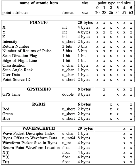
6至10型的点由不同成分组成的“数据层”的组合表示。类型6至10的组成详见下表: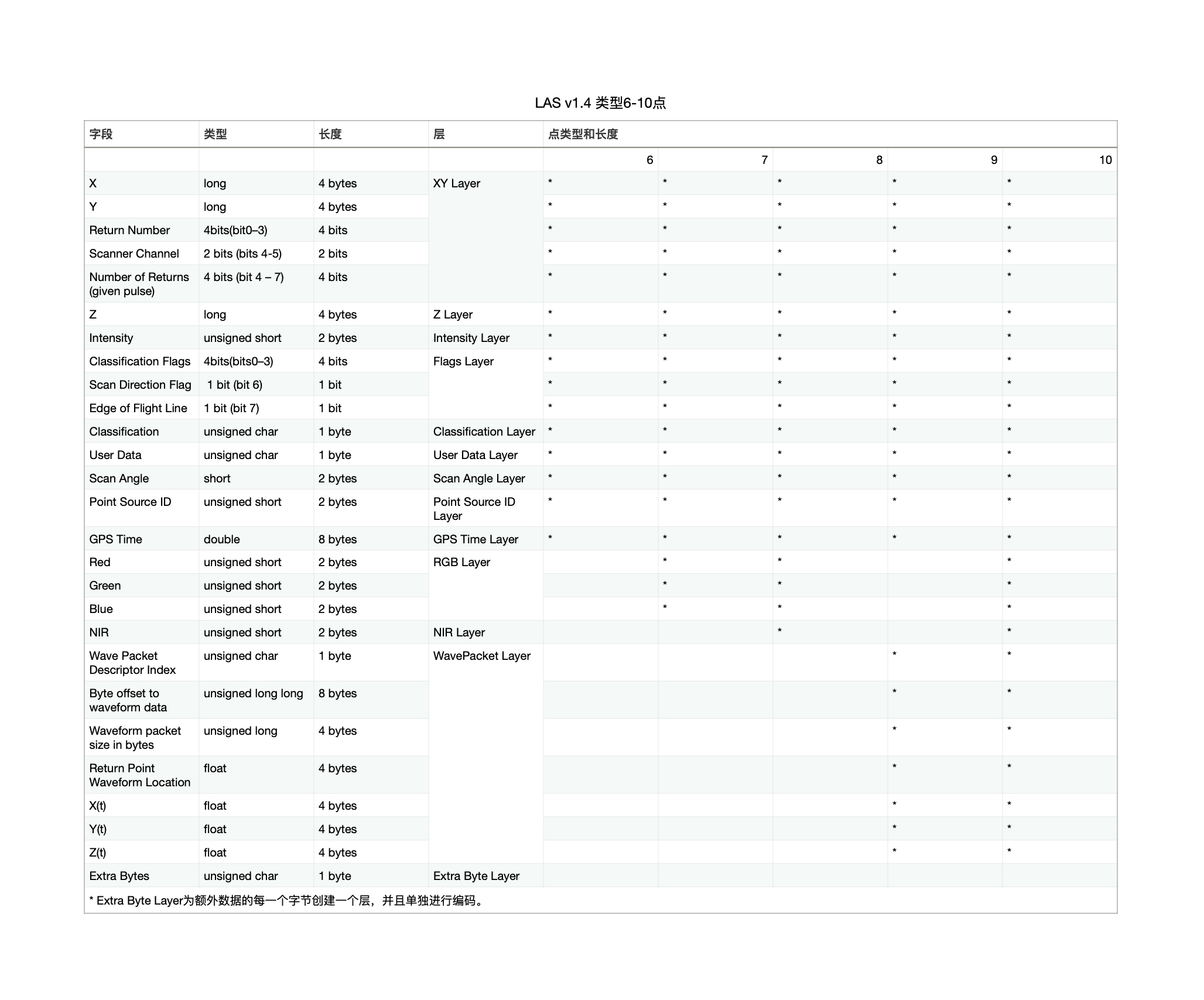
对每种数据LASzip设计了不同的压缩器。由不同成分组成的不同类型点可以复用这些压缩器,实现模块化复用。在每个数据块的开始,LASzip存储了第一个点的原始数据,并且初始化编码器。该点的数据用来作为后续预测的初值,之后每个点的数值全部依次进行编码。
LASzip采用了基于自适应的基于上下文的算术编码器对数值进行差分编码。对于每种不同的成分,采用不同策略进行压缩,追求最高的压缩率。详情可以参考文献。
测试数据来自于众包地图构建中生成的一些道路点云数据集。数据集格式是二进制编码的pcd文件,在后续测试中,pcd格式文件的大小也是压缩率的基准。在本次测试中,一共准备了8组测试数据。
本文对LASzip的压缩性能进行了一些测试,下表对LASzip压缩测试结果进行了总结。
| 项目 | PCD | LAS | LASzip | GZIP |
|---|---|---|---|---|
| 平均压缩倍率(源文件大小/压缩后文件大小) | 1.0 | 0.42 | 4.61 | 1.52 |
| 编码+输出文件速度(万点/秒) | - | 21.3 | 17.8 | - |
| 解码速度(万点/秒) | - | - | 51.8 | - |
| 点云存储效率 | 0.900 | 2.119 | 0.195 | - |
| LICENSE | BSD | LGPL | LGPL | zlib license |
| LIBRARY | PCL | PDAL Libels | Laszip Pylaz | zlib |
根据表格中的结果,可以得到以下结论:
总的来说,LASzip具有压缩倍率高,无损,编解码速度快,受到业界广泛支持等优点,特别适用于高精地图和众包地图业务。在众包地图业务中,已经集成了LASzip作为点云存储格式。目前,比较流行的LASzip编解码库主要是LASzip,lazperf, 和PDAL。下面对这三种库进行比较。
| LASzip | Lazperf | PDAL | |
|---|---|---|---|
| License | LGPL | LGPL | LGPL |
| 支持LASzip v1.4 | 是 | 否 | 是 |
| 语言 | c | c++ | c++ |
| 编码 | 是 | 是 | 是 |
| 解码 | 是 | 是 | 是 |
| 复杂功能 | 否 | 否 | 是 |
| 依赖其他第三方软件 | 否 | 否 | 是 |
| 是否符合车规 | 否 | 否 | 否 |
SimpleLight is a project I participate in Turku University. It’s an easy-to-use, web based remote control LED lamp.
Programmer: Gao Changyu, Qian Jiayan, Yang Xuerui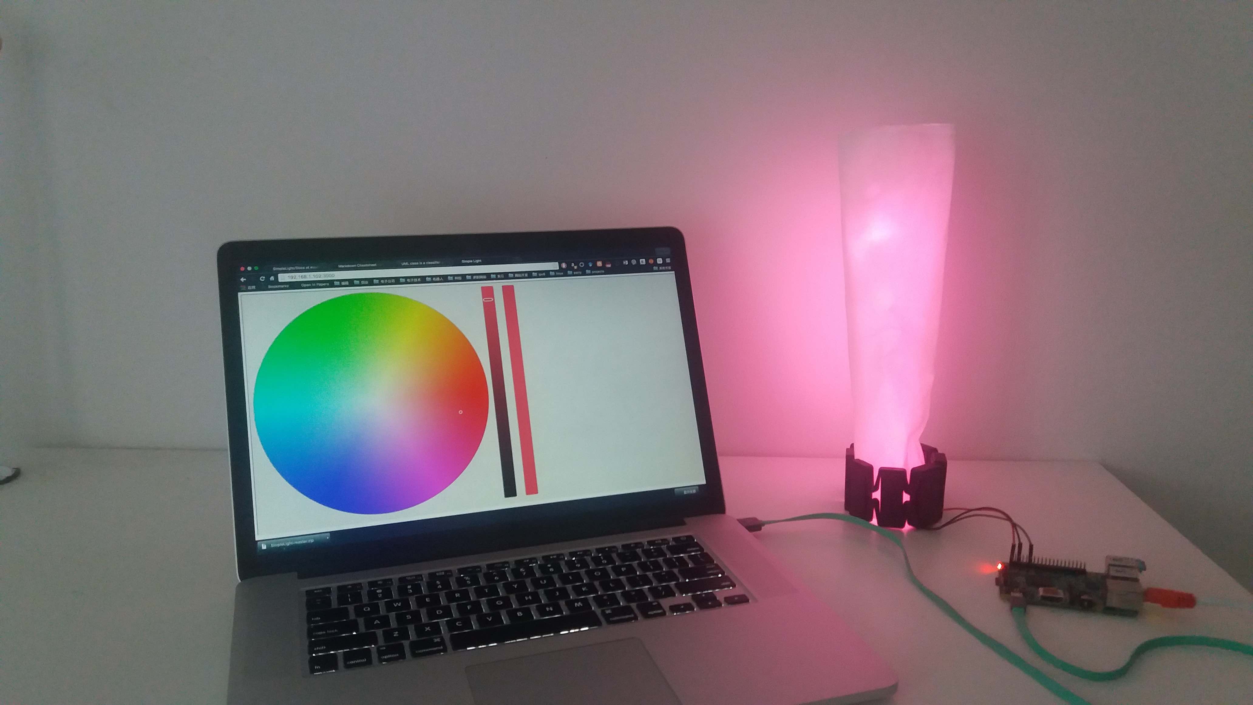
The hardware is quite simple. We got 4 adafruit neopixel(ws2812b) led and connect them serially. The data in port is connected to pin 18, vcc and gnd are connected directly to raspberry pi.
The project is configured for raspberry pi 2B. Before running the code, you need to install some dependencies.
when asked the root password of mysql, use 123456.
run the ws2812b controller:
$ sudo ~/light_control_project/ws2812b_controller/ws2812b_raspberry_pi2
run the webpage server:
$ nodejs ~/light_control_project/server/SimpleLight.nodejs
run the Myo Connect adapter:
$ python ~/light_control_project/PyoConnect_v1.0/light_control.pyoc
Connect raspberry pi to a router, then you can access the webpage at http://ip_of_raspberry_pi:3000. You should be able to change the light color of the leds through a palette (in mode one).
Myo connect is also supported. you can use double click gesture to change the visual effect.
All the documents about the project are in Docs folder.
a learning journal about class diagram.
I found a very useful website on this topic:reference.
Basically, now I know the meaning of different connections:
In this blog, I will record the working progress in the capstone project and the problems I faced.
Working Content: Today I tested the mavlink steaming rate of miniAPM. The original APM3.2.1 firmware support up to 25 Hz of message streaming. This is limited by the software, So I modified the firmware and successfully increased the rate to 50Hz. In fact the rate can be improved to up to 100 Hz. But I’m afraid this will harm the stability of the firmware.
In ArduCopter.pde, The scheduler update rate of gcs_data_stream_send() is set to 50Hz. This function is the regarding to the streaming of message. The function is in GCS_Mavlink.pde.
1 | \* |
In this function data_stream_send() is called, each stream is sent based on the following statement.
1 | if(stream\_triger(STREAM\_RAW\_SENSORS)) { |
The limit occurs in stream_triger(), as shown below:
1 | if (stream\_ticks\[stream\_num\] == 0) { |
This is already my modified version. The stream_ticks is count down at 50 Hz. So when rate > 25, the streaming rate can not increase any more. So when rate > 25, I set the stream_ticks[stream_num] to 0, so they rate will go up to 50 Hz.
Time: 3 hour.
Working Content: I figured out how every channel is used in Arducopter. channel 1 ~ channel 4 are used for throttle, roll, pitch, yaw. channel 5 is used for mode switch. channel 6 is optionally used for tuning and camera. channel 7 and above are aux switch for more functions. I think I can add a new auxilary function to switch on and off off-board mode. and connect the receiver’s channel 6 to channel 7. then we can use channel 6 on transmitter to toggle off-board.
Working Content: I modified the pixy node and add a ros publisher. It doesn’t work at first with rosrun. Latter I found in the official guide of installation that I need to copy the /src/host/linux/pixy.ruls to /etc/udev/ruls.d reference.
Time: 1 hour.
Working Content: I finally found the way to upgrade the firmware of the miniAPM. Before I tried to use the mission planner to upgrade the miniAPM but the transmission always fail. Today I downloaded an APM Planner to my mac and succesfully upgraded miniAPM to arducopter 3.2.1. In this version “arming” through mavlink is implemented. More over when the mavlink connection is down, the control will fail over to transmitter when RC_OVERRIDE is used. That’s also a good news.
Today I also modified the firmware source code of ArduCopter. I’m trying to enhance the failsafe feature in RC_OVERRIDE. I will enhance the code based on the orignal Arducopter 3.2.1 because that’s the newest firmware supported by miniAPM.
Time: 3 hours.
Working Content: I tested the mavros arming service to arm the apm. It doesn’t work. But I don’t think it’s a bug of mavros. The mission planner cannot arm the apm neither.
I also tested the rcoverride function of mavros. It worked. The SYSID_MYGCS param of apm must be set to 1, so that the mavros can override the rc. But I found that once you use the rcoverride to take over the transmitter, you cannot use the transmitter to take over the mavros again. This would cause problem when I want to use the transmitter to take over the raspberry pi in emergency.
Improved the pan tilt control of pixy.
Time: 5 hours.
Working Content: Calibrate the lens distortion (radial and tangental distortion) of the pixy camera. We used the camera_calibration sample code of opencv 2.4.9 to calculate the camera matrix and distortion coefficients. The focus length of pixy camera is adjustable, so every time I adjust the focus length I need to re-calibrate the camera. It’s not convinient.
We use the following equations to calibrate the distortion:

The calibrated result is acceptable but not accurate. Because we are not sure the meaning of x, y and r. I’m afraid there are some mistakes in not calculation.
Time: 5 hours.
Working Content: Assembly and test fly the drone.
Time: 5 hours.
Working Content: Assembly the drone.
Time: 5 hours.
Working Content: Assembly the drone; Change the color marker recognition method from four different colors to two different colors.
Time : 5 houts.
Working Content: update the CMakeList.txt of pixy_node. fix the compiling failure.
Time: 3 hours.
Working Content: Checkout the mavros and mavlink submodule. fix the conflict of the submodules.
Time: 4 hours.
Working Content: Improve the simulation environment. The apm sitl firmware is not realistic, and we would like to use PX4 autopilot stack. So I compiled the px4 sitl firmware on linux and upgrade gazebo to version 6.0.
Time :8 hours.
Working Content: Set up the simulation environment in linux. The simulation environment includes the apm sitl firmware, the ros and gazebo simulation environment. I tested the simulation and it works.
Time: 8 hours.
ROS is a popular and useful software framework in robotics area. Gazebo is a powerful robotic simulator. Ardupilot provide a tutorial for sitl simulation in ROS/Gazebo environment. I tried to setup this environment in my mac. Here I share the record of my steps.
Install Ubuntu 14.04.3
sudo apt-get install gitmkdir workspacecd workspacegit clone https://github.com/alexbuyval/ardupilotcd ardupilotgit checkout RangeFinderSITL2sudo sh -c 'echo "deb http://packages.ros.org/ros/ubuntu $(lsb_release -sc) main" > /etc/apt/sources.list.d/ros-latest.list'sudo apt-key adv --keyserver hkp://pool.sks-keyservers.net --recv-key 0xB01FA116sudo apt-get updatesudo apt-get install ros-indigo-desktop-fullsudo rosdep initrosdep updateecho "source /opt/ros/indigo/setup.bash" >> ~/.bashrcsource ~/.bashrcsudo apt-get install python-rosinstallmkdir -p ~/catkin_ws/srccd ~/catkin_ws/srccatkin_init_workspacecd ~/catkin_ws/catkin_makeecho "source $HOME/catkin_ws/devel/setup.bash" >> ~/.bashrcsource ~/.bashrcecho $ROS_PACKAGE_PATH/home/developer/catkin_ws/src:/opt/ros/indigo/share:/opt/ros/indigo/stackssudo apt-get install ros-indigo-octomap-msgs roscd
cd ../src #Navigate in your ROS user source files directory
git clone https://[email protected]/alexbuyval/arducopter_sitl_ros.git
git clone https://github.com/PX4/mav_comm.git
git clone https://github.com/alexbuyval/rotors_simulator.git
git clone https://github.com/ros-drivers/joystick_drivers.git
git clone https://github.com/ethz-asl/glog_catkin.git
git clone https://github.com/catkin/catkin_simple.git
git clone https://github.com/ethz-asl/gflags_catkin.git
cd rotors_simulator
git checkout sonar_plugin
cd ../..
wstool init src
wstool set -t src mavros --git https://github.com/alexbuyval/mavros.git
wstool update -t src
rosdep install --from-paths src --ignore-src --rosdistro indigo -y
roscdcd ..catkin_makesudo apt-get install gawkecho 'PATH="$PATH:/home/developer/workspace/ardupilot/Tools/autotest"' >> ~/.profilesudo apt-get install python-pipsudo pip install pymavlinkcd ~/workspace/ardupilot/ArduCoptersim_vehicle.sh -f arducopter_sitl_ros --console